#line differential
In Korea, transmission lines are composed of voltage levels of 765kV, 345kV, and 154kV.
The relays responsible for protecting these transmission lines are divided into primary protection elements and backup protection elements.
This chapter will first offers the fundamental principles of the highly reliable 87 relay used for protecting 154kV transmission lines, which have a lower voltage level.
The basic principle of the 87 relay is based on Kirchhoff’s law, which states that the sum of the incoming and outgoing currents is zero. Please refer to the diagram below.
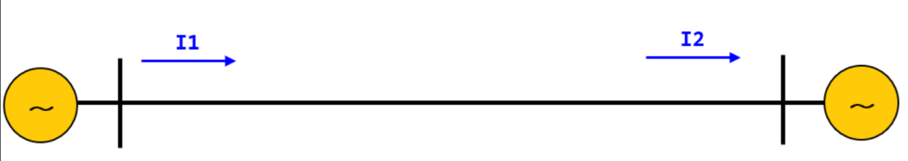
Figure 1. Explanation for the load flow between the two substations
In the above figure, I1+I2=0. This can be easily understood as the current flowing from the transmission end to the distribution end.
Let’s now find out how the 87L protection relay recognizes and judges the current.
By the way, the “87” in 87L means current differential, and “L” indicates Line, so it is understood as line protection current differential.
(So, by applying the “T” in 87T to Transformer, it can be understood as transformer protection current differential.)
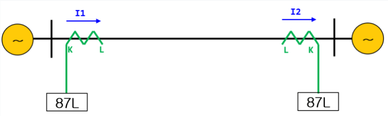
[Figure 2. Connection method for normal conditions and 87L/CT]
In the picture above, when the normal current flows from left to right, the current of I1 goes through K first and then through L to become I2.
On the diagram, I2 flows through L first and then through K. This can be expressed by the following equation,
I1 + (-I2) = 0, which can be rewritten as I1 – I2 = 0. If a current of 5A flows as the secondary value of current, then it would be 5A – 5A = 0.
The (-) sign is to be understood as the sign that occurs when compared with I1 and has a phase difference of 180 degrees.
This result of 87L becomes the fault current for normal operating conditions.
The important point here is to connect the direction of the CT for the current input of both ends of 87 to the target for protection (meaning the transmission line).
Even if the polarity changes, it is possible to change the direction in the relay coordination, but in Korea, the principle is to determine the direction based on the CT wiring to prevent Human Error, even if the polarity changes.
So let’s see how the current flowing through the transmission line changes when a fault occurs.
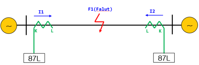
[Transmission Line Fault Current Flow]
When a fault occurs, the current flows to the faulty transmission line.
When comparing normal conditions and faulty conditions,
- Normal condition: I1 (current flows from K to L), I2 (current flows from L to K)
- Fault condition: I1 is the same as the normal condition, I2 (current flow changes from K to L)
When summarizing these conditions, applying the Kirchhoff’s circuit law (KCL) yields
I1+I2 does not equal 0, but rather the total current of I1 and I2 increases, and this becomes the differential current.
In terms of understanding, if I1 is 5A and I2 is 5A, the differential current under normal conditions is 0, but under faulty conditions, the differential current is 10A.
The differential current value is used for a relay, which is a type 87 relay.
Here is the translation of the provided paragraph: “So far, this has been an explanation of the concept for detecting differential current for 87L, and understanding the 87 relays applied to transformers, generators, reactors, capacitors, etc. will be very helpful if approached with the same concept.”
In this chapter, the key word is to understand that the connection of the transformer and CT is different in both directions.
If the CT terminal is set in one direction, the current may be detected even under normal conditions, so be careful when connecting the CT on site as it can operate even in load current.
If you have any further questions, please inquire in the comments.

답글 남기기