– Siemens 7SD/ Current Differential Relay/ Line differential Relay/Restraint Current/SIP5_7SD

SIEMENS 7SD models of current differential relays are classified into SIP4 and SIP5 grades. SIP4 represents the 4th generation, while SIP5 represents the 5th generation relays. The 7SD (SIP4: 7SD5, SIP5: 7SD8)_87L, as a current differential relay model for transmission lines, has a unique restraint current calculation method, which can sometimes be challenging. Therefore, I would like to explain the calculation method for restraint current .
The 87 relay, based on Kirchhoff’s Current Law (KCL), is one of the most reliable protection schemes available. It is engineered to provide complete zone protection, ensuring that any internal faults are swiftly isolated while remaining secure against external faults. This relay must reliably clear internal faults and avoid tripping for faults outside its protection zone.
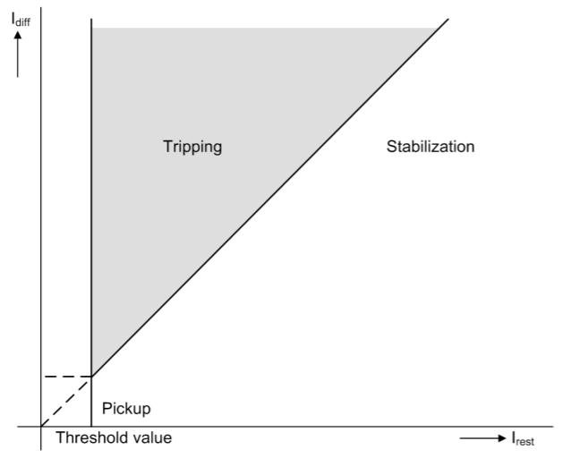
So, now let’s take a look at the trip characteristics of the Siemens 7SD Model for 87 relay. The trip characteristics of the current differential relay are determined by the ratio of differential current to restraining current, and the operating setting value of the differential current.
The X-axis in the figure represents the restraining current, the Y-axis represents the fault current, and the trip area is formed according to the set value (pick-up threshold).
Current differential protection (CDP) is calculated as the vector sum of the input currents, which is expected to be the same for most relays. However, in this document, we want to explain the unique method of calculating the restraining current of the Siemens 7SD model compared to other manufacturers. (Because the content in the manual is difficult to interpret)
for Restraint Current Calculation
I rest = Pickup(87 Setting parameter) + CT Error + Signal Error + Synch Error
As mentioned earlier, it can be considered as Siemens’ Concept to clearly distinguish between internal and external accidents and understand the part related to possible errors when 87 relay includes it in the restraint current.
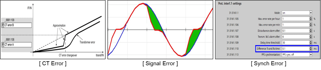
The First “CT Error “ refers to the error in the current input, and this error increases in magnitude as the current increases, based on the experience. Siemens has set a reference point (CT Error transition) and applied the CT error ratio based on this.
For example, if I1 current is 5A and I2 current is also 5A, with CT Error A (3%), CT Error B (15%), and CT Error transition (1.5), then I1 (5A) * 3% + I2 (5A) * 3% = 0.15 + 0.15 = 0.3A. If this value exceeds the reference point, a 15% error ratio should be applied.
The Second “Signal Error” analysis involves analyzing distorted current waveforms and the difference in fundamental frequencies to suppress the included current. This analysis and processing are performed automatically by algorithms and applied without any adjustments.
The third “Sync Error” is applied to prevent malfunctions from external faults due to the current difference between the TX and RX communication lines, which occurs during communication between both ends. The applied method increases the suppression current to prevent malfunctions from external faults.
The calculation method used
Delta t = Input current * 2 * π(3.14) * f * Parameter value (Tx and Rx Time).
The restraint current for these three conditions is calculated as the sum of all 87 relays connected.
Conclusion: Unlike conventional manufacturers of differential protection relays, the Siemens 7SD model adopts a method that fixes the slope and adds an error element to the restraining current, instead of setting the restraining current as a scalar sum and adjusting the slope.
Siemens : Adds on restraint Current with Error(CT, Signal,Synch)
I hope my posts are helpful, and I would be grateful if you leave a comment or subscribe.
If you have more questions, please leave a comment.
We will incorporate your feedback to include more valuable information in the next post!
Home page : http://www.joy-2024.com
Always ready to help !

익명 에 답글 남기기 응답 취소